Electronic Design has a long history of Ideas for Design (IFD) articles contributed by readers. This is the very first IFD instance. It appeared in the 1955 February issue of Electronic Design. This was the second year of Electronic Design’s publication. One or more IFDs typically appeared in each Electronic Design issue while it was a print magazine through the early 2000s. It is now an online-only publication. The IFD series continues to this day.
- Bill Wong, Senior Content Director, Electronic Design
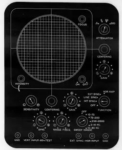
THE HYPOTHETICAL oscilloscope control panel shown at the right was designed according to the principles of human engineering. I believe that it would be particularly easy and natural to operate, especially for the operator who would not have used the instrument before.
Let us analyze the oscilloscope. Here we have two forms of input information; signal leads from the observed circuit and input controls on the oscilloscope face (frequency, amplification, and position). These input controls may be subdivided into the vertical group, the horizontal group and the functional group. The output information is displayed on the screen of the cathode ray tube.
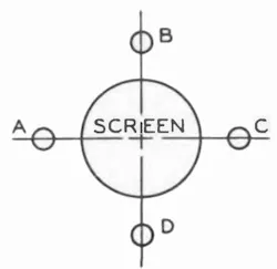
In attempting to arrive at a logical panel layout for the face of an oscilloscope, the input and output information must be organized to operate naturally. That is, to be psychologically acceptable. For example, let us consider the vertical centering control. It may be located anywhere around the cathode-ray tube screen shown in Fig. 1. The controls are located directly on the centerlines of the screen for maximum effect. If located at .1, a clockwise rotation of the control would move the signal display down. A counterclockwise rotation would move the display up. If located at C, these relative motions would be reversed. That is, a clockwise rotation would move the display up. Locations B and D offer no natural rotational direction for a vertical control. A horizontal centering control would work in a similar manner, having natural positions at B and D, but not at A or C.
 hole diagram
1. This diagram helps demonstrate that the "natural” positions for vertical centering controls are at A and C, and at B and D for horizontal centering.
In the hypothetical design illustrated, the vertical centering control has been placed at C and the horizontal control has been placed at D. These positions were picked over their alternates, because for the average right-handed operator, the hand would not cover the tube screen while making adjustments. The related horizontal and vertical controls (gain, sensitivity, and attenuation) are aligned on both sides of their respective centering controls: the horizontal controls aligned horizontally and the vertical controls are aligned vertically. The centering controls are directly aligned with their respective centerlines of the tube screen.
The cathode ray tube controls (focus and intensity) are placed directly on the bezel of the tube. These locations immediately associate these controls with the tube. The remaining functional controls are placed below and to the side of the horizontal controls, in a balanced, though not necessarily in a symmetrical arrangement. The input jacks are placed across the bottom of the panel. This allows the input leads to lie flat on the work table, where they cannot be disconnected accidentally.
Tube Position
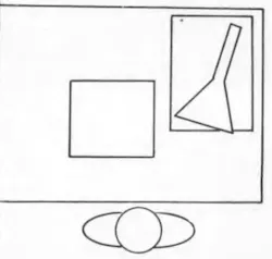
With the oscilloscope on the right side of the work table, which is the natural side for note taking by a right-handed observer, the offset (nonsymmetrical) arrangement places the output display closer to the observer. A further improvement, shown in Fig. 3, would be to place the tube diagonally in the cabinet, thus allowing the observer to always have a head-on, undistorted view of the screen, even though the oscilloscope is not directly in front of the observer.
 layout knob diagram
3. The observer (bottom) can see the scope display much easier if the tube is mounted diagonally.
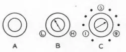
The knob dials are of three types, as illustrated is Fig. 2. Type A has no markings and is used only for visual positioning of another display. In this case, observing the screen while making the adjustments for centering. Type B has an arrow on the knob and terminal markings on the face panel. This is used for relative adjustments. That is, a “more or less” type of adjustment without a particular quantity needed Type C has an arrow on the knob and a full range of subdivision markings on the face panel. In the cast of selector switches, each position should be marked. For continuously adjustable controls, we divide the range into ten parts. It has been found that, no matter what the size of a dial, we get the best relative accuracy when the distance between markers is about 0.6”.
 knob diagram
2. These three types of "human-engineered" rotational knobs have different functions.
The principles of human engineering on which this design is based can be extended to all electronic devices, while some of the features of this oscilloscope can be incorporated directly in other instruments For example, meter faces could be placed near one side or another of a panel face, and are even more easily mounted diagonally or on pivots than CR tubes.
 scope diagram
4. This hypothetical oscilloscope panel was designed according to human engineering methods.
More Electronic Design Ideas for Design


Source: Electronic Design